Andrew Birkett's nobugs.org
Hacking futaba receivers
(March 2006)
Introduction
As part of my “build a uav” project, I’d like to access the raw PPM signal which is broadcast using FM. I’ve got a six channel receiver, and I don’t really want to use up six input pins on my microcontroller. When you see inside the receiver box, you’ll see a RF board with lots of inductors and capacitors, and a digital board containing a shift register (used to demultiplex the signal) and the output servo connectors. So basically I want to grab the signal before it gets to the decoder board, because I can do the decoding myself.
Opening the box
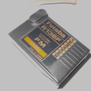
This is the receiver, as most people will know it. There’s seven three-pin connectors on the side. Six of these are the channels which you control from the transmitter. The last one is for the power connector.
And this is what it looks like when you pop the lid off. To do this, find a small screwdriver and push it gently into the four small slots. At the same time, gently prise the two halves apart with your thumbnail. You can see on the photo that there’s just plastic hooks holding it together (click on the photo for a bigger version). The PCB inside is a snug fit inside the plastic casing, but apart from that it isn’t glued or screwed in place.
Inside the box
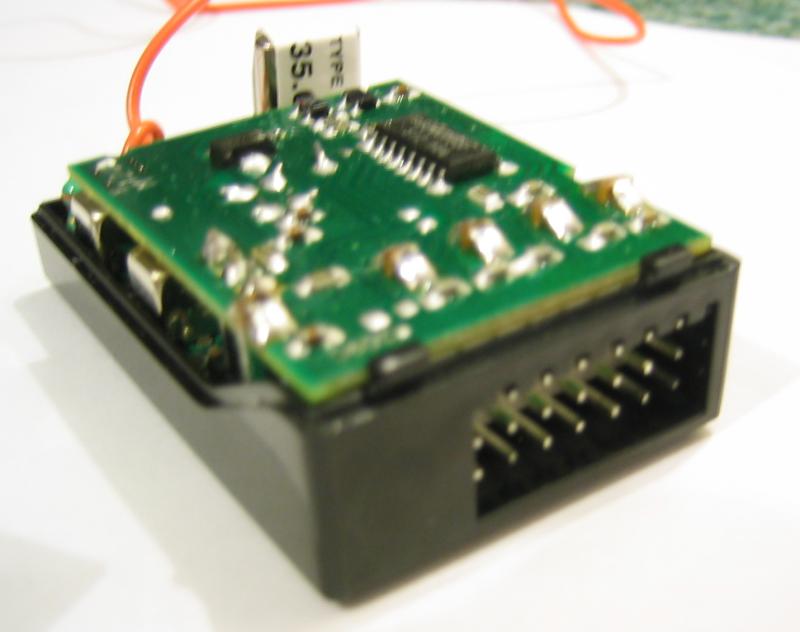
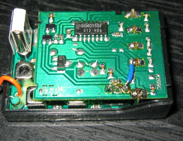
Now we can see inside! The top board has a BU4015BF shift register on it, and is connected at right angles to a small board which holds a capacitor (bottom right of the photo) and the 3x7 pin header. The top board is joined to the bottom board by a similar pin-header connection. The bottom board is largely filled with inductors, and there’s a couple of sizable capacitors sandwiched between the boards. Finally, the crystal can be seen at the top-left.
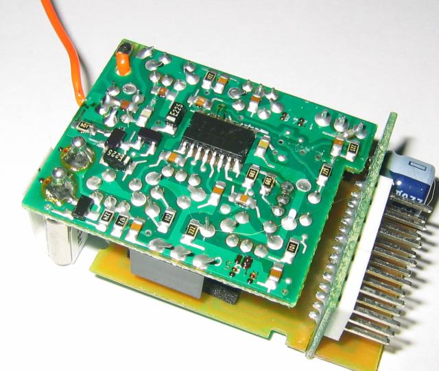
So now I’ve flipped the board upside-down. You can see the 7791F RF decoder chip and a variety of passive components. You can also see the separate connector board and the power-supply smoothing capacitor.
Finding signals
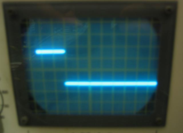
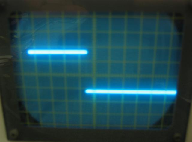
These two photos show the output from servo-ouput 3 (throttle) at maximum and minimum throttle positions. I didn’t take note of the oscilloscope settings, but I know that these will be pulses of 1ms and 2ms respectively. This is the signal for a single channel. Now I need to find the signal for the all-in-one channel.
Result!
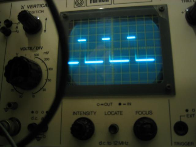
This is what I’m looking for. This is a PPM (pulse position modulation) signal which is feeding into the shift register clock pin. When I move the joysticks on the transmitter, I can see the high-pulses moving left and right.
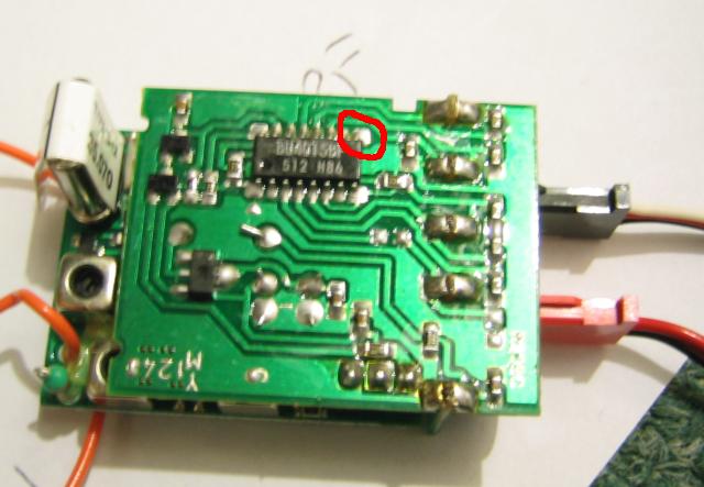
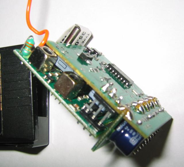
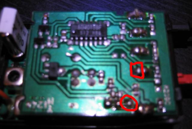
And here (circled in red) is where I found the signal. Now, I’m going to do a bit more prodding around to find out where it’ll be easiest to solder an extra wire onto the circuit board. The pin is on the corner and has a fairly large solder pad, but there’s probably a better/easier place. Also, I imagine the middle pin of the “power” connector is unused so it’ll probably be fine to connect the PPM signal out there. Again, I need to do a bit more checking there.
The mod
In the end, I decided to solder an extra wire between the two marked locations. The pin at the bottom is one of the three (power, gnd and signal) which go between the RF board and the digital board. I connect it to the “signal” pin on the battery connection. The power and ground pins on the servo connections are all interconnected anyway, so there’s nothing special about the one marked “battery”. The red battery lead just doesn’t make any connection to the signal pin, unlike the servo leads. So I decide to co-opt the spare pin as a way of bringing the multiplexed signal out in a neat way. This means I can still use the rx as normal too.
And here is the result of my soldering - an extra wire bringing the multiplexed signal out onto the servo connections. The servo connection daughter board is firmly fixed to the digital board by the row of five soldered connections you see on the right of the photo. Each of these is a separate pair of two connections. I just prodded them with a multimeter to figure out which one went where. Oh, I also had to Dremel out a small amount plastic from the inside of the rx lid to make enough space for my extra wire. It’s a tight fit inside the rx box!